
Ray Cogliano & Z
Rhythm Cartridge 707 (RC-707) DRUM MACHINE

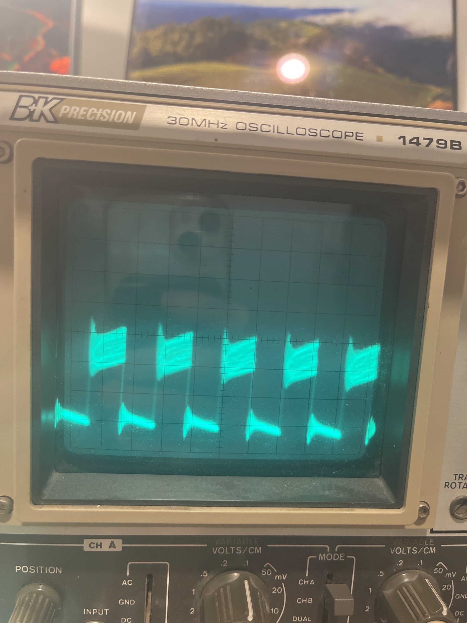
Output signal before and after Low Pass Filter


“Midi Tape Delay”
B
In the end I could not get the second tape head to pickup sound from the tape. I think due to an amplification problem. I will continue with this project later on in my free time but the debugging was too much for the timespan I had in this finals period.
Prototype Documentation
The RC707 is a drum machine with an 8 steps step sequencer and 4 tracks. The step sequencer uses buttons with LED lightning to tell which step is currently active and which step is currently the playhead is on.
The Mighty RP2040
For the main controller I opted for an Adafruit Metro RP2040. It is an Arduino UNO form factor board with a Raspberry Pi RP2040 on it. It contains two ARM Cortex-M0+ cores clocked at 133Mhz(you can overclock it up to 480Mhz I believe but in this project I just used the stock clock frequency), 264KB of SRAM, two SPIs and two I2C.
During the development process I also tried NXP iMXRT1011 Cortex-M7 MCU. It was pretty fast but the RAM was too little I ran out of RAM pretty quick.
Peripherals
For the LED driver I used AW9523 by Shanghai Awanic(上海艾为). It is a 16 channels constant current LED driver with 256 levels of brightness. It is controlled by I2C.
For the rotary encoder I used Adafruit I2C Stemma QT Rotary Encoder Breakout with NeoPixel. It is a very powerful breakout with an ARM core built-in! I can simply ask it to turn on/off the WS2812 and asks it how many step the user turned it. It communicates via I2C.
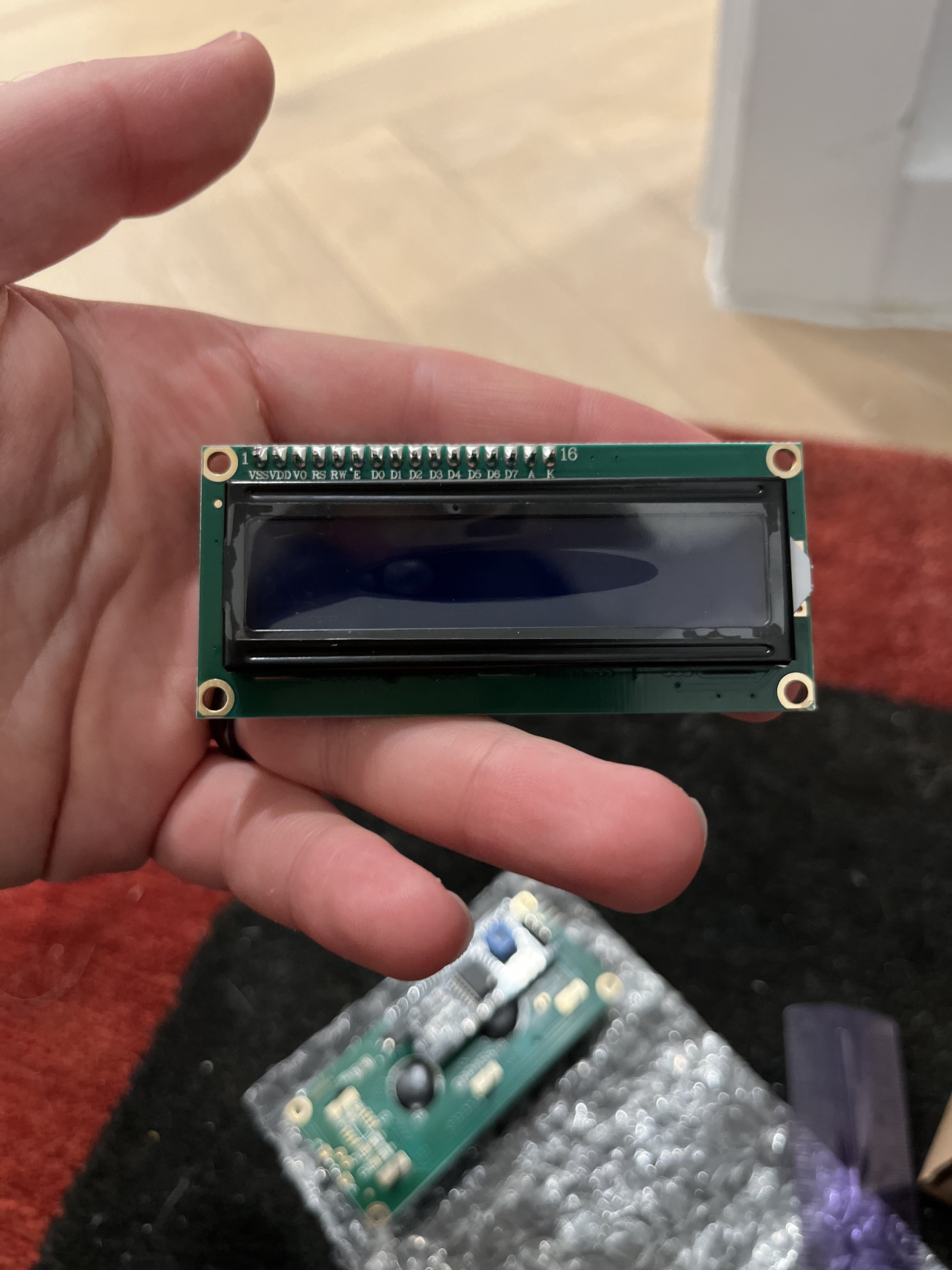
For the display I used an Adafruit Quad Alphanumeric Display. It uses a HT16K33 compatible chip and drives 4 14-segments alphanumeric characters. It also uses I2C to communicate with the MCU.
Sound Generators
The sound generator cards are what made this project interesting. Since these boards are hot swappable (self initialise on power up) the drum machine player is able to change sound on the fly.
Each sound generator contains a controller chip and a single capacitor to make it more stable. The sound is stored inside the controller chip and played back at a per-determined rate when IO1 is triggered. Unlike the midterm version of the sound module, the final version has re-triggering enabled since it's a drum machine.
Those sound generators are one time programmable(OTP) and audio data are not supposed to be changed after the assembly.
PWM output smoothed by Ray's LPF. Without the Low-Pass Filter, the PWM outcput would not be able to be fed into any other audio-input devices without potentially damaging the reciever.
Control
Use the rotary encoder to update the BPM. Use play button to play and use mode button to switch mode. The drum machine has two modes: LIVE and STEP mode.
In LIVE mode the first 4 buttons of the sequencer acts as drum pads and triggers sounds of 4 sound modules accordingly.
In STEP mode it works as a regular step sequencer. The user can edit the track they selected in LIVE mode.
Everything on the control interface runs asynchronously. It is possible to press all buttons at once and expect everything reacts.
Programming
I programmed this project with CircuitPython. It was definitely a challenge at the beginning but onc I got the hang of it it was pretty smooth.
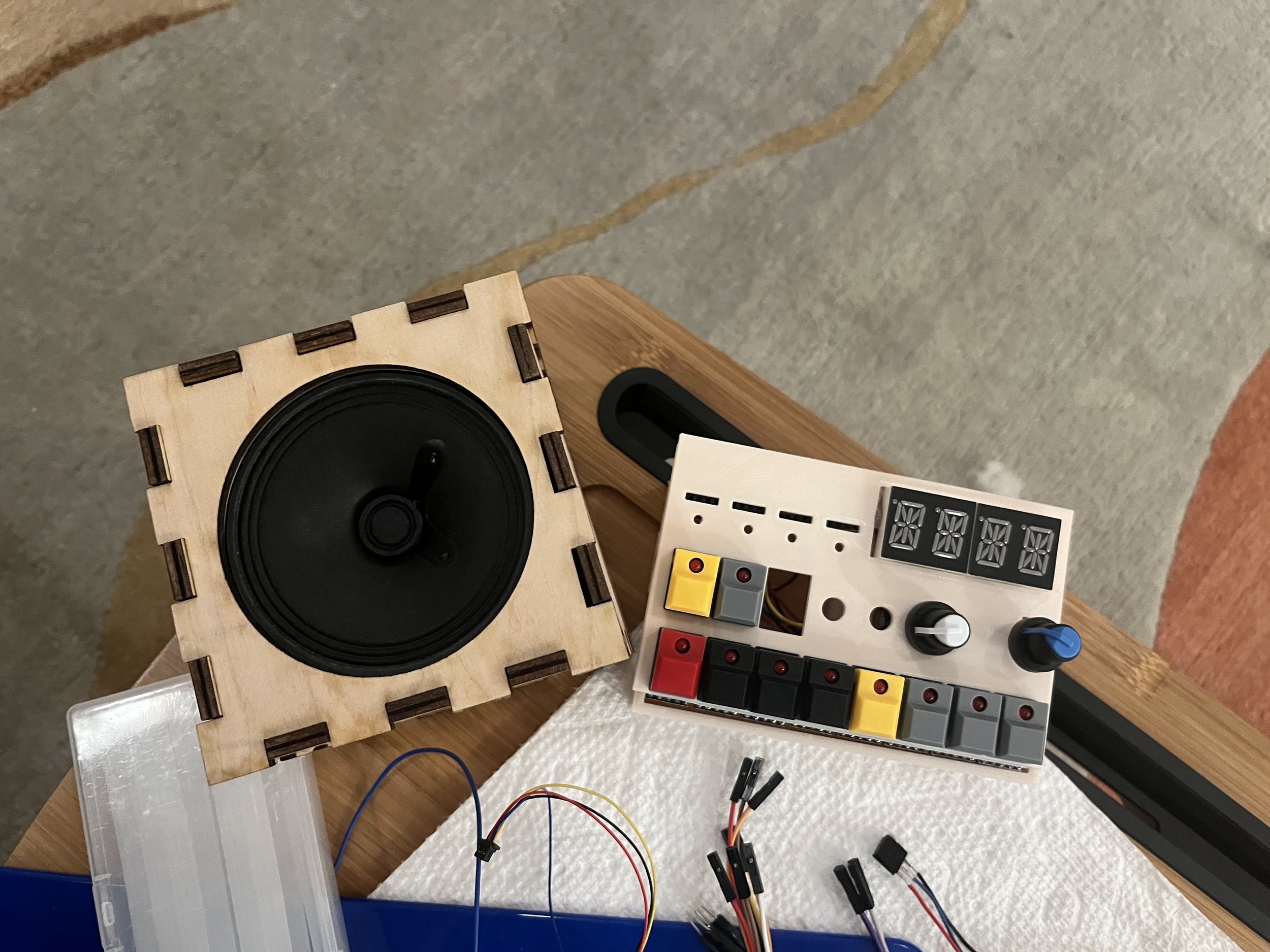
User-Interface Design
In my design approach for the drum machine layout I wanted to keep the device as small as possible while having a clear and consise approach for users. As a next step that I didn't get to I would make clear labels on each function as well as labeling each sound chip with their sounds.
One big issue for user assessiblity is forcing the user to change between live mode and step mode. A change I would like to make in future iterations is adding a button underneath each sound module to let the user change to each sound in a clearer way. Going between Live and Step mode had to be done because of IO limitations but it created an issue of putting the user into a "menu diving" mode for composing. This interface is clear to many musicians who have used drum machines before but its very inaccessible to non-musicians. There is definitely a disconnect and inpractacility between the physicality of having the user use replaceable cartridges for sound sources and menu diving for sound selection.
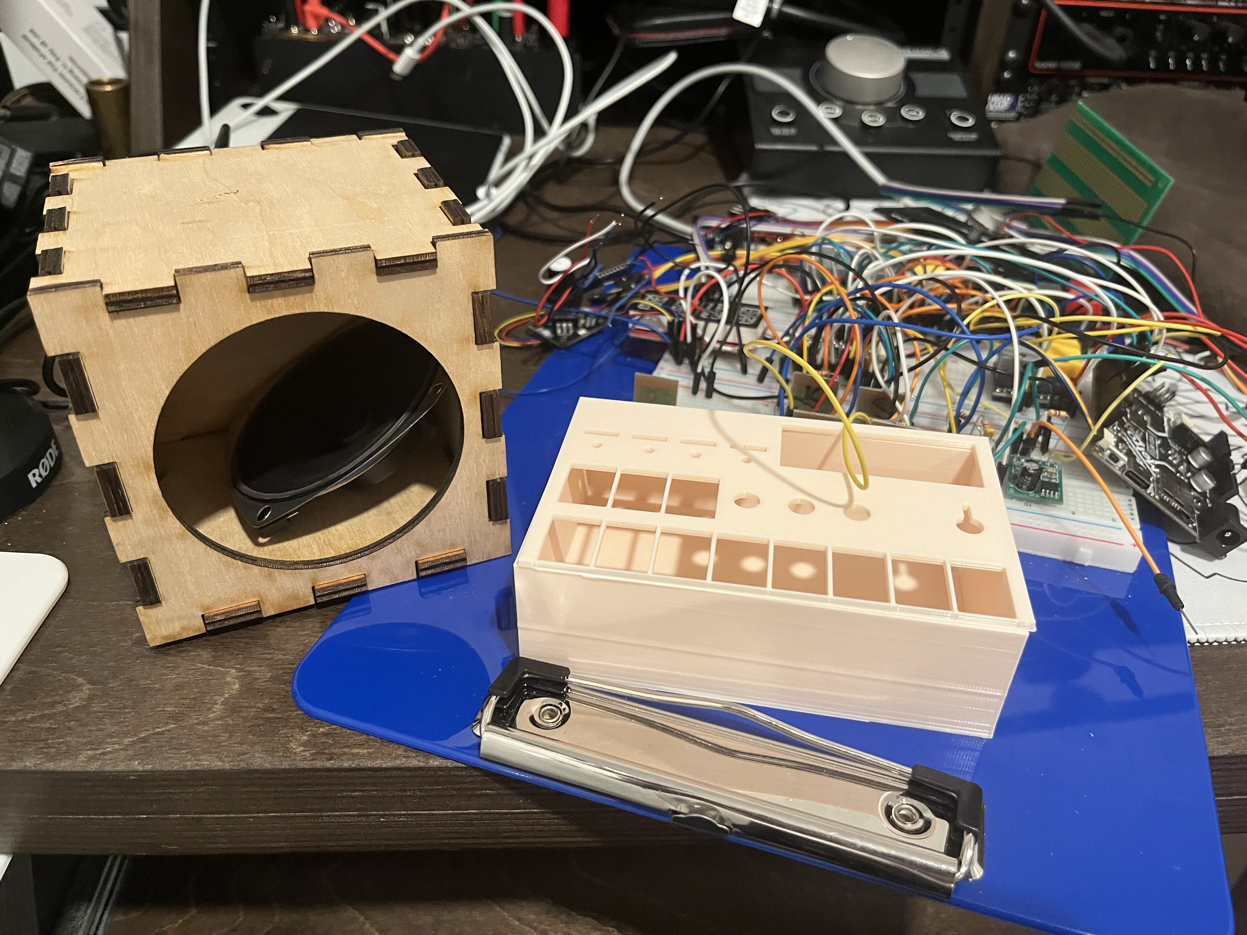
This is my first real experience making an enclosure for a device and I ran into many more issues than I had imagined. The height of the case started out short but as I condensed the final circuit from 3 breadboards to 0.75 of a (sawed off) breadboard, I found that it became more impossible to fit the device into a small case.
Additionally the time required to hand solder leads to each of the buttons and components took up a huge portion of my time spent on this project. In the future I would like to move towards making PCBs in any device that is worthy of an enclosure rather than enclosing a hand-soldered protoboard or breadboard.
In retrospect I wish I had made the device wider to more easily fit the amount of components and wiring in. In the end the top of the case had to be glued shut so the components did not pop out of the top of the case. Also I would like to learn how to be make snap-in components out of PLA so assembly for cases such as this are easily able to be put together and taken apart.
“Ghost TRanslator”
Ray Cogliano & Henrique Stockler
B


Documention Part 1


Here I controlled a servo motor using a touch capacitive resistor. I realized my previous issues were because I had the arduino misaligned one row further into the breadboard than the diagram, so I ended up using the wrong pins for input and output by accident. Not sure how I still ended up with a noisy output that was semi-functional in the speaker lab.
Here I connected a touch capacitive resistor to the arduino’s analogRead input and uploaded a program that makes the frequency of the tone react to the touch resistors value. It seems like there’s a lot of noise induced in the signal, I really don’t know why.
Here I connected a speaker to the arduino and tested the output.
Here I connected an LED in parallel with the DC motor. Both are controlled by the push button simultanously. The brightness of the light is matching the decrease and increase in speed of the DC motor.
Here I held the DC motor upright as I pressed the push button. The motor behaved as expected. I was anxious of getting shocked by holding the DC motor.
Here I connected a DC motor to a push button for the first time. I did not expect the DC motor to run as fast as it did when I first turned it on so it immediately disconnected its own leads from itself as it went flying.
Here I connected three buttons in series. Each button has the same behavior turning on a single LED. Multiple buttons pressed at the same time does not change the behavior.
Here I connected a potentiometer to the LEDs input. Turning the potentiometer clockwise caused the LED to get brighter and turned the potentiometer counterclockwise caused the LED to get dimmer until it’s off state.
Here I measured the Voltage drop of the two LEDs in series. I measured a peak of 1.82 Volts when the button was pushed on and a low of 0.00 Volts while the button was released.
Here I attached a second LED in series with their on/off states being controlled by a push button. I connected one of the second LED’s leads directly into a breadboard hole in front of the first LED to save myself the effort of connecting a wire between the two. I noticed the brightness of both LEDs are equal but overall less bright than a single LED.
Here I measured the Voltage drop across the push button with the multimeter. Using the same V— 20 mode as before, I measured a peak of 2.12 Volts when the button is pushed ON and 0.00 Volts when the buttons is in its OFF state.
Here I connected a button to an control the on/off of the LED with its being default in the off state.

Here I measured the Voltage across an LED using a multi-meter.The LED was being supplied with stable power from the Arduino. I set the multi-meter to V— 20 for measuring DC power and a range of 2.00-19.99 Volts. I ended up measuring 2.05 Volts across each leg of the LED.

Here I powered the arduino using a power supply connected to a DC power jack adapter instead of using my computer to power the arduino.

Here I attached LED across the center lanes, connecting it to the negative lane from the right side. and the positive lane from the left side.

Here I built the first LED circuit. I used the Arduino to power the LED and attached the resistor directly into the positive power lane on one end.